
August 12, 2026
Large Payload Injection Molding Robots: How to Calculate Robot Payload Correctly
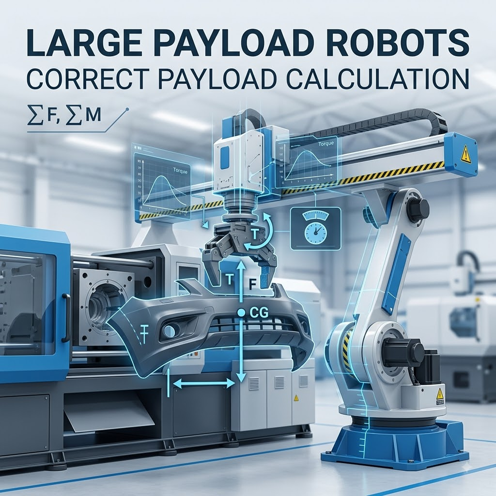
Introduction: Why Correct Payload Calculation Matters in Injection Molding Automation
In modern plastic manufacturing, automation is no longer only about increasing production speed. It is also about improving consistency, reducing labor dependency, protecting product quality, and maintaining stable production over thousands of cycles.
However, when companies invest in automation, one of the most common mistakes I have seen is selecting an injection molding robot based only on the weight of the plastic part.
A 5 kg molded component does not always require a 5 kg robot.
The actual requirement can be much higher after considering:
· End-of-arm tooling (EOAT)
· Gripper structure
· Vacuum components
· Sensors
· Cooling fixtures
· Sprue handling mechanisms
· Dynamic movement forces
This is where understanding Large Payload Injection Molding Robot selection becomes important.
A correctly calculated payload ensures that the robot operates within its mechanical limits, maintains cycle stability, reduces wear, and avoids unexpected downtime.
In this guide, we will explain how to calculate robot payload correctly for injection molding applications, what factors engineers should consider, and how manufacturers can select the right heavy-duty automation solution.
Table of Contents
1. What Is a Large Payload Injection Molding Robot?
2. Understanding Robot Payload in Injection Molding Applications
3. Why Payload Calculation Is More Than Product Weight
4. Robot Payload Calculation Formula Explained
5. Step-by-Step Payload Calculation Method
6. Factors Affecting Large Payload Robot Selection
7. Common Applications of Heavy Duty Injection Molding Robots
8. Real Manufacturing Example
9. Common Payload Selection Mistakes
10. FAQ
11. Conclusion
What Is a Large Payload Injection Molding Robot?
A Large Payload Injection Molding Robot is an automated robotic system designed to handle heavier loads during plastic injection molding operations.
Compared with standard injection molding robots, large payload models are developed for applications where the combined weight of the product, tooling, and additional equipment exceeds normal robot capacity.
Typical applications include:
· Large automotive plastic components
· Industrial plastic housings
· Appliance parts
· Plastic pallets and containers
· Heavy engineering plastic products
These robots are commonly integrated with:
· Injection molding machines
· Automatic part removal systems
· Conveyor systems
· Vision inspection equipment
· Packaging automation
The purpose is not simply lifting heavier parts.
The robot must also maintain:
· Position accuracy
· Repeatability
· Cycle speed
· Smooth motion
· Long-term mechanical reliability
For industrial robot safety and integration, manufacturers commonly follow international standards such as ISO 10218, which defines safety requirements for industrial robots and robot applications.
Understanding Robot Payload in Injection Molding Applications
Many purchasing teams misunderstand the meaning of robot payload.
The rated payload of an industrial robot does not mean:
“The robot can lift this much plastic product.”
Instead, payload refers to the total mass attached to the robot wrist, including the tooling and the workpiece.
According to industrial robot terminology, payload includes all components attached to the robot manipulator, including the end-effector and workpiece.
For injection molding automation, the payload usually consists of:
Payload Component | Example | Included in Calculation? |
Plastic Product | Automotive housing, container, cover | Yes |
Runner / Sprue | Remaining molded material | Yes |
Gripper | Mechanical or vacuum gripper | Yes |
EOAT Frame | Aluminum structure, brackets | Yes |
Sensors | Detection devices | Yes |
Cables and Pneumatic Components | Tubes, fittings | Yes |
Additional Fixtures | Cooling or inspection fixtures | Yes |
A common engineering mistake is calculating only:
Product Weight = Required Robot Payload
This calculation is usually incomplete.
Why Payload Calculation Is Critical for Injection Molding Automation
Injection molding robots often operate continuously.
A factory producing automotive components may run:
· 16–24 hours per day
· Hundreds of thousands of cycles per year
· Multiple production shifts
Small calculation errors can create large problems over time.
An overloaded robot may experience:
· Reduced acceleration performance
· Increased vibration
· Lower positioning accuracy
· Higher motor and gearbox stress
· Shortened service life
In practical projects, I usually recommend leaving sufficient payload margin instead of selecting a robot that operates close to its maximum rated capacity.
A robot running at 95–100% payload may work during testing, but production conditions are different.
Real factories have:
· Faster cycle requirements
· Emergency stops
· Tool changes
· Different material batches
· Temperature variations
These factors affect actual robot performance.
How to Calculate Injection Molding Robot Payload Correctly
Basic Robot Payload Calculation Formula
The basic calculation method is:
Required Robot Payload = Product Weight + EOAT Weight + Additional Equipment Weight + Safety Margin
A simplified example:
Item | Weight |
Plastic Product | 8 kg |
Sprue Material | 1 kg |
Gripper | 5 kg |
Tooling Frame | 4 kg |
Sensors and Accessories | 1 kg |
Total Load | 19 kg |
Adding a safety margin:
19 kg × 1.25 = 23.75 kg
In this case, selecting a robot with approximately 25 kg payload capacity would be more reasonable than choosing a 20 kg model.
Step 1: Calculate Molded Product Weight
The first step is identifying the actual part weight.
This information usually comes from:
· Product CAD data
· Material density calculation
· Injection molding simulation
· Trial production results
For example:
A polypropylene automotive interior component:
· Material: PP
· Part weight: 6.5 kg
This is only the starting point.
The robot does not handle only the finished product.
Step 2: Add Runner and Sprue Weight
Depending on mold design, the robot may remove:
· Finished product
· Runner system
· Sprue
· Multiple cavities at one time
Example:
A four-cavity mold:
· Each part: 2 kg
· Runner system: 3 kg
Total plastic load:
(2 kg × 4) + 3 kg
= 11 kg
This is why understanding the complete molding process is necessary before selecting a robot.
Step 3: Calculate End-of-Arm Tooling Weight
The EOAT is often underestimated.
For large injection molding applications, the tooling may include:
· Steel mounting plates
· Multiple grippers
· Vacuum generators
· Pneumatic cylinders
· Sensors
· Cooling channels
A heavy EOAT can consume a significant percentage of the robot payload.
Example:
Robot rated payload:
50 kg
EOAT weight:
18 kg
Remaining capacity:
32 kg
The robot is not actually handling a 50 kg product.
It is handling only the remaining capacity.
Step 4: Consider Dynamic Loads and Motion Conditions
Payload calculation is not only a static weight problem.
Robot movement creates dynamic forces.
Important factors include:
· Acceleration
· Deceleration
· Robot speed
· Tool offset distance
· Center of gravity position
A heavy tool mounted far away from the robot wrist creates additional torque.
This means:
A compact 30 kg load close to the wrist may be easier to handle than a 20 kg load with a long extension.
Many robot manufacturers provide payload charts considering wrist moment and inertia limitations, not only maximum kilograms.
Step 5: Apply Safety Margin
A practical safety margin is commonly added because real production conditions change.
Typical engineering considerations:
Application Condition | Suggested Margin |
Stable simple handling | 10–15% |
Normal industrial production | 20–30% |
Heavy tooling / high-speed movement | 30%+ |
The correct margin depends on:
· Robot design
· Motion profile
· Production requirements
· Manufacturer recommendations
Advanced Payload Calculation Methods for Injection Molding Robots
In real production environments, calculating robot payload is not as simple as adding several weights together.
For small plastic components, a basic calculation may be enough.
But for Large Payload Injection Molding Robots, especially those handling automotive parts, industrial housings, or multi-cavity molds, engineers need to consider additional mechanical factors.
A robot can technically lift a certain weight, but that does not always mean it can move that load safely at the required production speed.
This is where many automation projects fail.
The mistake is usually not the robot itself. The mistake is that the application requirements were underestimated during the selection stage.
Understanding Payload Moment and Center of Gravity
One important concept in robot selection is payload moment.
Payload is not only about kilograms.
The position of the load also matters.
A 30 kg tool mounted directly near the robot wrist creates a different mechanical load compared with a 30 kg tool extended 800 mm away.
The further the weight moves away from the robot axis, the greater the torque applied to the robot joints.
A simplified formula:
Payload Moment = Load Weight × Distance from Robot Wrist
Example:
Application | Weight | Distance | Moment |
Compact gripper | 30 kg | 300 mm | 9 kg·m |
Extended tooling | 30 kg | 800 mm | 24 kg·m |
Although the weight is identical, the second application creates almost three times more moment load.
This affects:
· Robot acceleration
· Joint stress
· Repeatability
· Service life
For large injection molding automation projects, engineers normally review both:
· Maximum payload capacity
· Wrist allowable moment and inertia
The robot catalog payload rating alone is not enough.
Dynamic Load Considerations During Robot Movement
Injection molding robots usually operate with repeated high-speed movements:
· Enter mold area
· Remove product
· Rotate or reposition
· Place parts on conveyor
· Return to standby position
These movements generate acceleration forces.
The actual load during motion can exceed the static weight.
Factors influencing dynamic loading include:
· Robot speed
· Acceleration settings
· Motion distance
· Tool design
· Part gripping method
For example:
A robot removing a heavy automotive bumper component may not have difficulty holding the part.
The challenge is moving it quickly and accurately without vibration.
This is why a Heavy Duty Injection Molding Robot often uses:
· Higher rigidity mechanical structures
· Stronger servo motors
· Reinforced wrist mechanisms
· Optimized motion control systems
Industrial robot manufacturers commonly design injection molding automation systems with different payload classes because applications range from small pick-and-place operations to heavy industrial handling.
Matching Robot Payload With Injection Molding Machine Size
Robot selection should always be connected with injection molding machine specifications.
A larger injection molding machine usually means:
· Larger molds
· Larger products
· Heavier components
· Longer extraction distance
However, machine tonnage alone does not determine robot payload.
A 1000-ton injection molding machine may produce lightweight thin-wall products, while a 300-ton machine may produce a heavy engineering plastic component.
The correct selection requires looking at:
· Mold dimensions
· Part weight
· Number of cavities
· Cycle requirements
· Removal direction
· Automation process
A practical relationship is:
Injection Machine Size | Typical Robot Requirement |
Small molding machine | Standard pick-and-place robot |
Medium molding machine | Servo robot with moderate payload |
Large molding machine | High payload robot system |
Extra-large molding system | Heavy-duty industrial robot integration |
Many injection molding automation suppliers provide robots designed specifically for large molding machines, including systems with higher payload capability and customized grippers.
Large Payload Injection Molding Robot Applications
A Large Payload Injection Molding Robot is typically selected when the molded products are too heavy, too large, or too complex for standard automation systems.
Automotive Plastic Components
Automotive manufacturing is one of the most demanding areas for robotic injection molding automation.
Common applications include:
· Instrument panels
· Door panels
· Bumper components
· Battery covers
· Large interior trims
· Structural plastic components
These parts often require:
· High repeatability
· Stable cycle time
· Careful handling to avoid surface damage
Automotive suppliers frequently combine robots with:
· Vision inspection
· Conveyor systems
· Secondary assembly stations
Robotic systems are also used in more complex injection molding processes such as insert loading and over-molding applications.
Large Household Appliance Components
Appliance manufacturers use heavy payload robots for:
· Refrigerator interior parts
· Washing machine housings
· Air conditioner components
· Large plastic covers
The challenge is usually not only weight.
Large parts often require:
· Long reach
· Wide working area
· Careful gripping
A poorly designed gripper can cause:
· Surface marks
· Deformation
· Part dropping
Industrial Plastic Products
Industrial applications include:
· Storage containers
· Plastic pallets
· Equipment housings
· Agricultural plastic products
These products are often produced with:
· Large molds
· Long cycle times
· Heavy material usage
Automation helps manufacturers maintain stable output with fewer manual handling operations.
Real Manufacturing Case Study: Robotic Handling of Automotive Injection Molded Components
A practical example can be seen in automotive electronics manufacturing.
In one publicly documented application, KUKA robots were integrated into an automotive production system at Possehl Electronics for manufacturing vehicle control housings.
The robots performed precision handling tasks involving stamped inserts and injection molding processes, achieving accurate placement within tight production cycles.
The project demonstrates an important point:
The robot is not selected only according to part weight. The complete system must consider:
· Insert handling
· Mold positioning
· Cycle synchronization
· Production reliability
For large plastic components, the same engineering principle applies.
A successful automation cell requires coordination between:
· Injection molding machine
· Robot payload capability
· End-of-arm tooling
· Safety system
· Production workflow
Selecting the Correct End-of-Arm Tooling (EOAT)
The robot itself is only one part of the automation system.
The EOAT often determines whether the application succeeds.
For injection molding robots, common EOAT designs include:
Vacuum Grippers
Used for:
· Flat plastic panels
· Large smooth surfaces
· Lightweight components
Advantages:
· Simple structure
· Fast operation
· Low product marking risk
Mechanical Grippers
Used for:
· Complex shapes
· Heavy products
· Components requiring stronger holding force
Advantages:
· Higher gripping reliability
· Suitable for irregular geometry
Combined Tooling Systems
Large payload applications often combine:
· Vacuum cups
· Mechanical fingers
· Sensors
· Rotation mechanisms
This increases tooling weight, which must be included in payload calculations.
Common Engineering Mistakes When Selecting Large Payload Robots
Mistake 1: Calculating Only Product Weight
Incorrect:
Product weight = robot payload
Correct:
Product + runner + tooling + accessories + safety margin
Mistake 2: Ignoring Tool Center of Gravity
A lightweight but extended tool can create high wrist torque.
Engineers should evaluate:
· Tool length
· Weight distribution
· Rotation requirements
Mistake 3: Choosing Maximum Payload Without Margin
Operating near the robot limit may reduce:
· Speed
· Accuracy
· Reliability
A properly sized robot usually performs better over long production periods.
Mistake 4: Ignoring Future Production Changes
Some factories later add:
· Different molds
· New products
· Additional sensors
· More complex tooling
A small additional payload reserve can provide valuable flexibility.
Payload Calculation Example for a Large Injection Molding Application
Assume a factory produces a large automotive plastic housing.
The estimated load:
Component | Weight |
Plastic Part | 18 kg |
Runner System | 4 kg |
Mechanical Gripper | 12 kg |
Sensor System | 2 kg |
Tool Frame | 8 kg |
Total Static Load | 44 kg |
Add 25% engineering margin:
44 kg × 1.25 = 55 kg
Recommended robot selection:
A robot rated around 60 kg payload capacity would provide a more comfortable operating range.
This allows room for:
· Motion acceleration
· Tool changes
· Production variation
Part 2 Summary
Selecting a Large Payload Injection Molding Robot requires a complete engineering evaluation.
The correct payload calculation should consider:
· Product weight
· Runner weight
· EOAT weight
· Center of gravity
· Dynamic movement
· Safety margin
A robot that appears powerful on paper may not perform well if the application calculation is incomplete.
In the next section, we will continue with:
How to Select the Right Large Payload Injection Molding Robot Supplier
Choosing a supplier for a Large Payload Injection Molding Robot project is not only a purchasing decision. It is an engineering decision that affects production efficiency, maintenance costs, and long-term factory performance.
Many companies focus mainly on the robot payload number and purchase price.
However, after working with industrial automation projects, one thing becomes clear:
A robot system is only as reliable as the engineering behind the complete application.
A suitable supplier should understand not only robotics, but also:
· Injection molding processes
· Mold structure
· Product handling requirements
· End-of-arm tooling design
· Factory automation integration
Key Factors When Evaluating an Injection Molding Robot Supplier
1. Injection Molding Automation Experience
A general industrial robot supplier may have strong robotic knowledge, but injection molding applications have unique requirements.
A supplier with injection molding experience should understand:
· Mold opening and closing timing
· Robot entry and exit positions
· Part release conditions
· Cooling requirements
· Cycle time optimization
For large molded parts, small timing errors can affect the entire production cycle.
The supplier should be able to analyze the complete process instead of simply supplying a robot arm.
2. Payload Range and Robot Structure
A large payload robot should not only have sufficient lifting capacity.
Engineers should evaluate:
Evaluation Item | Why It Matters |
Rated payload | Determines maximum handling capability |
Wrist moment | Controls mechanical stress |
Repeatability | Affects positioning accuracy |
Reach distance | Determines mold accessibility |
Motion speed | Influences cycle time |
Servo performance | Affects stability |
For injection molding applications, repeatability is often more important than maximum speed.
A robot that moves slightly slower but maintains stable accuracy may create better overall production results.
3. End-of-Arm Tooling Capability
The robot supplier or automation partner should understand EOAT design.
A good tooling solution considers:
· Product geometry
· Material characteristics
· Surface protection
· Weight distribution
· Mold release conditions
For example, a glossy automotive interior panel may require a different gripping method compared with a thick industrial container.
The wrong gripper design can create:
· Surface marks
· Product deformation
· Increased rejection rate
Cost Considerations for Large Payload Injection Molding Robots
The investment cost of a robotic injection molding system includes more than the robot itself.
A complete automation project may include:
Cost Component | Description |
Robot System | Robot arm, controller, software |
EOAT | Grippers, vacuum systems, sensors |
Integration | Installation and programming |
Safety Equipment | Guards, sensors, safety controls |
Conveyor System | Product transfer and handling |
Maintenance | Spare parts and service |
Initial Cost vs Long-Term Production Value
A common mistake is selecting the lowest-priced robot system.
In manufacturing environments, the cheapest initial investment does not always create the lowest total cost.
A better evaluation considers:
· Production uptime
· Maintenance frequency
· Energy consumption
· Cycle efficiency
· Operator requirements
· Product quality stability
For example:
A robot that reduces cycle time by only a few seconds may create significant annual savings in a high-volume factory.
Example: Production Efficiency Improvement Calculation
Assume:
· Production runs 20 hours/day
· 300 working days/year
· Cycle time improvement: 5 seconds
Annual production time saved:
20 × 60 × 300 = 360,000 minutes
The saved production capacity can be significant.
This is why automation decisions should consider the complete manufacturing impact rather than equipment price alone.
Future Development Trends of Large Payload Injection Molding Robots
The injection molding automation industry is changing quickly.
Several trends are influencing future robot development.
1. Smart Manufacturing and Data Monitoring
Modern factories are increasingly adopting Industry 4.0 technologies.
Large payload robotic systems are becoming connected with:
· Production monitoring software
· Machine data collection systems
· Predictive maintenance platforms
· Remote diagnostics
The goal is to identify problems before unexpected downtime occurs.
For example:
A robot controller can monitor:
· Servo motor load
· Movement patterns
· Error frequency
Abnormal changes may indicate mechanical wear before failure happens.
2. Higher Demand From Electric Vehicle Manufacturing
The growth of electric vehicles is creating new applications for large plastic components.
Examples include:
· Battery covers
· Charging system housings
· Lightweight structural components
· Thermal management parts
These applications often require:
· Larger molds
· Higher precision
· More complex handling systems
This increases demand for higher payload automation.
According to the International Federation of Robotics (IFR), automotive manufacturing remains one of the largest users of industrial robots globally, with continued investment in automation technologies.
Source: International Federation of Robotics (IFR), World Robotics reports.
3. Flexible Automation Systems
Manufacturers increasingly need production flexibility.
Instead of building one robot system for one product only, factories prefer automation cells that can handle:
· Multiple molds
· Different product sizes
· Product variations
Future Large Payload Injection Molding Robots will increasingly focus on:
· Easier programming
· Faster tool changes
· Modular EOAT design
· Better software integration
Frequently Asked Questions About Large Payload Injection Molding Robots
What is considered a large payload injection molding robot?
There is no universal definition because robot payload classes vary by manufacturer.
Generally, large payload injection molding robots refer to systems designed for handling heavier products, larger tooling, or complex end-of-arm systems beyond standard pick-and-place applications.
Typical applications include automotive components, industrial plastic parts, and large molded products.
How do I calculate the correct payload for an injection molding robot?
The basic calculation is:
Required Payload = Product Weight + Runner Weight + EOAT Weight + Additional Equipment + Safety Margin
You should also consider:
· Center of gravity
· Wrist moment
· Acceleration forces
· Robot working speed
The final selection should always be confirmed with the robot manufacturer.
Is a higher payload robot always better?
Not necessarily.
An oversized robot may increase:
· Equipment cost
· Energy consumption
· Floor space requirements
The goal is not choosing the largest robot.
The goal is choosing the correct robot capacity with appropriate engineering margin.
What safety margin should be used for robot payload calculation?
The required margin depends on the application.
Typical considerations:
· Simple handling: around 10–15%
· Standard industrial handling: around 20–30%
· Heavy tooling or dynamic movement: potentially higher
The final value depends on robot manufacturer specifications and application conditions.
Can one robot handle different injection molding machines?
Yes, but only if:
· Payload requirements are compatible
· Reach is sufficient
· Interface systems are designed correctly
· Programming changes are manageable
Flexible automation systems are becoming more common in modern factories.
How often should injection molding robots be maintained?
Maintenance schedules depend on:
· Operating hours
· Payload level
· Working environment
· Manufacturer recommendations
Regular maintenance usually includes:
· Lubrication checks
· Mechanical inspection
· Cable inspection
· Calibration verification
· Software diagnostics
Preventive maintenance is generally more cost-effective than repairing unexpected failures.
Final Conclusion: Choosing the Correct Large Payload Injection Molding Robot
Selecting a Large Payload Injection Molding Robot is not simply about finding a robot that can lift a certain weight.
The real challenge is understanding the complete relationship between:
· Product weight
· Tooling design
· Robot mechanics
· Injection molding process
· Production requirements
A correct payload calculation helps manufacturers achieve:
· More stable production
· Longer equipment life
· Better product quality
· Lower operating risk
The most reliable automation projects usually start before the robot is purchased.
They begin with careful engineering analysis.
From calculating the real payload, evaluating the center of gravity, designing suitable EOAT, and selecting the right automation partner, every decision affects the final production result.
For factories investing in injection molding automation, the question should not be:
“Which robot has the highest payload?”
The better question is:
“Which robot payload capacity matches our actual production requirements with enough reliability for years of operation?”
That approach leads to smarter investment decisions and more sustainable manufacturing performance.