
September 18, 2026
Single-Axis vs. Multi-Axis Servo Take Out Robots: Which Is Right for Your Injection Molding Machine?
I have been sourcing take out robots and injection molding automation for over a decade, and I can tell you that the most expensive mistake in this category is not buying the wrong robot. It is buying a robot with the wrong number of axes — and discovering the limitation six months later when a new part geometry arrives.
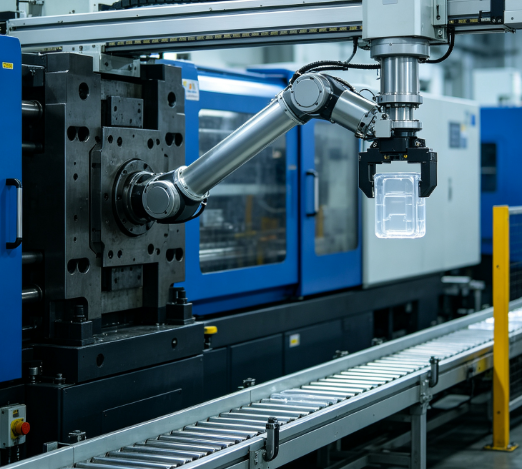
1. Introduction: The Axis Decision That Determines Your Automation Ceiling
I have been sourcing take out robots and injection molding automation for over a decade, and I can tell you that the most expensive mistake in this category is not buying the wrong robot. It is buying a robot with the wrong number of axes — and discovering the limitation six months later when a new part geometry arrives.
Here is what that looks like in practice. A molder buys a single-axis servo robot because the current production is a simple two-plate mold producing a small electrical connector. The robot picks the sprue, drops it into the granulator, and the cycle runs beautifully. Twelve months later, the customer introduces a new product line — a glass-filled nylon housing with a delicate latch that requires part removal with orientation. The single-axis robot cannot grip the part. It cannot rotate it. It cannot place it in a tray. The molder is now facing a second robot purchase, and the first robot — barely a year old — is already obsolete for the new work.
The axis configuration determines what the robot can do. A single-axis robot can execute a straight-line pick and place. A three-axis robot can execute a three-dimensional path and perform insert loading. A five-axis robot can rotate, flip, and orient the part in any direction. The axis count is the ceiling on your automation capability. And the decision should be made based on the parts you will run over the next three to five years, not just the parts you are running today.
The global take out robot market continues to expand, driven by labor shortages, quality demands, and the integration of vision systems and AI algorithms into complex part-handling applications. The take out robot is moving from a simple sprue picker to a programmable automation asset. This guide breaks down the axis configurations — single-axis, two-axis, three-axis, and five-axis — across the parameters that matter for procurement: function, cycle time, precision, tooling compatibility, cost, and the decision framework that prevents the under-specification mistake.
2. What “Axis” Actually Means in a Take Out Robot
Before comparing configurations, let me define what an axis is in the context of a take out robot. An axis is a controlled direction of motion. Each axis adds a degree of freedom, and each degree of freedom expands what the robot can do.
Traverse (X-axis). The horizontal motion that moves the robot arm across the molding machine from the mold area to the drop position. This is the primary axis on every take out robot. On a single-axis robot, the traverse is servo-driven while the other motions are pneumatic.
Vertical (Z-axis). The up-and-down motion that lifts the part out of the mold and positions it at the drop height.
Crosswise or kick (Y-axis). The motion that moves the arm into and out of the mold area, perpendicular to the traverse direction.
Rotational axes (A, B, C). Rotary motions that allow the robot to rotate the part around one or more axes. These are the axes that enable part orientation, flipping, and angled extraction.
The key principle. The three primary linear axes (X, Y, Z) handle most standard take out applications: entering the mold, gripping the part, extracting it, and placing it on a conveyor or into a bin. The rotational axes add the ability to orient the part — to rotate it so that a delicate feature does not contact the conveyor, to flip it so that a stacking feature faces upward, or to angle it so that a complex geometry clears the mold during extraction.
Fewer axes means lower cost, simpler programming, and fewer maintenance points. More axes means greater flexibility, higher precision, and the ability to handle complex parts and secondary operations.
3. Single-Axis: The Sprue Picker That Does One Job Well
A single-axis robot — also called a sprue picker or swing-type runner take-out robot — has one servo-driven axis, typically the traverse or the swing motion. The vertical and crosswise motions are driven by pneumatic cylinders. The robot is designed for one job: removing the sprue or runner from the mold after the mold opens.
Function. A single-axis runner take-out robot is used in injection molding cells where the main automation task is sprue or runner removal. Instead of providing full multi-axis part extraction, it focuses on a controlled take-out motion for runner or sprue removal. The robot swings or traverses into the mold area, grips the sprue with a simple gripper or suction cup, extracts it, and drops it into a granulator.
Drive architecture. On a single-axis robot, the traverse stroke is driven by an AC servo motor while the vertical stroke and crosswise stroke are driven by pneumatic actuators. This hybrid architecture gives the robot precise positioning on the traverse axis — the axis that determines where the sprue is dropped — while keeping the cost down by using pneumatics for the other motions.
Typical applications. Single-axis robots are used for small to medium-sized presses — typically 30 to 300 tons clamping force — running two-plate molds with simple sprue removal requirements. Common products include small electrical connectors, USB housings, cable assemblies, and encapsulated electronics where the sprue is the primary component that needs removal. The robot covers the 30–300 ton IMM range and is designed for quiet operation with lower compressed-air draw than pneumatic-only alternatives.
The limitation. The single-axis robot cannot remove the part itself. It cannot orient the part. It cannot place the part in a tray or stack it. It is a sprue picker, not a part handler. If the application requires part removal — which most do — a single-axis robot is not sufficient on its own.
The cost. A single-axis servo swing-type runner take-out robot is the lowest-cost automation option in the take out category. The hybrid servo-pneumatic architecture keeps the cost down while providing servo precision on the most critical axis.
Single-Axis Robot Parameter | Typical Specification |
Servo axes | 1 (traverse or swing) |
Pneumatic axes | 2 (vertical, crosswise) |
IMM compatibility | 30–300 tons |
Payload | 1–3 kg (EOAT + runner) |
Cycle time | 2–4 seconds |
Primary function | Sprue/runner removal |
Part removal capability | No |
Orientation capability | None |
Relative cost | Lowest |
4. Two-Axis: The Cost-Effective Step Up
A two-axis robot adds a second servo-driven axis, typically the vertical stroke in addition to the traverse. The crosswise motion remains pneumatic. This configuration enables simple part stacking and faster cycle times than a single-axis robot.
Function. A two-axis robot can pick up the part, extract it from the mold, and stack it on a conveyor or in a bin. It cannot rotate or orient the part, but it can place it in a defined position. This is sufficient for many thin-wall packaging applications where the parts are simply stacked.
Drive architecture. The traverse stroke and the vertical stroke are driven by AC servo motors while the crosswise stroke is driven by a pneumatic actuator. The servo control on the vertical axis enables precise stacking height and controlled deceleration at the drop position.
Typical applications. Two-axis robots are suitable for the food industry and thin-wall packaging — plastic spoons, forks, thin-wall containers, and lids. Thin-wall products have high requirements for cycle time, and a two-axis take out robot can achieve a cycle time of approximately 4 seconds. When equipped with a belt conveyor, the two-axis traverse robot can pile up thin-wall products or spoons on the conveyor for downstream packaging.
The limitation. The two-axis robot cannot perform insert loading, in-mold labeling, or complex part orientation. It is a step up from the single-axis robot, but it is still limited to simple pick-and-place operations.
Two-Axis Robot Parameter | Typical Specification |
Servo axes | 2 (traverse, vertical) |
Pneumatic axes | 1 (crosswise) |
IMM compatibility | 80–500 tons |
Payload | 2–5 kg (EOAT + part) |
Cycle time | 3–5 seconds |
Primary function | Part removal + simple stacking |
Part removal capability | Yes |
Orientation capability | None |
Relative cost | Low-Moderate |
5. Three-Axis: The Industry Workhorse
A three-axis robot has all three primary linear strokes — traverse, vertical, and crosswise — driven by AC servo motors. This configuration provides full three-dimensional part manipulation and is the standard choice for the majority of injection molding automation applications.
Function. A three-axis robot can enter the mold, grip the part, extract it, traverse to the drop position, and place it with precision in a fixture, tray, or conveyor. It can perform insert loading — placing a metal insert into the mold before injection — and in-mold labeling. It can handle multi-cavity molds with multiple parts. It is the configuration that covers the widest range of applications.
Drive architecture. All three strokes of the main arm are driven by AC servo motors. If the robot has a sub-arm for sprue removal, the sub-arm strokes may be pneumatic. The full servo architecture on the main arm provides the precision and repeatability required for complex part handling.
Typical applications. Three-axis robots are the standard choice for regular shell parts, panel-type products, appliance and consumer goods housings, and any application that requires precise part removal, insert loading, or automated packaging. The typical repeatability is ±0.1mm to ±0.2mm, which is sufficient for most injection molding applications. Industry practice indicates that approximately 90% of standard injection molding products are best served by a three-axis robot, balancing cost and function.
The limitation. The three-axis robot lacks rotational axes. It can position the part in three-dimensional space, but it cannot rotate it. For parts with undercuts, deep cavities, or complex geometries that require rotation during extraction, or for three-plate molds and stack molds that require dual-arm operation, the three-axis configuration is not sufficient.
Three-Axis Robot Parameter | Typical Specification |
Servo axes | 3 (traverse, vertical, crosswise) |
Pneumatic axes | 0–1 (sub-arm, if equipped) |
IMM compatibility | 50–850 tons |
Payload | 3–15 kg (EOAT + part) |
Cycle time | 4–8 seconds |
Primary function | Part removal + insert loading + precision placement |
Part removal capability | Yes |
Orientation capability | Limited (no rotation) |
Repeatability | ±0.1–0.2 mm |
Relative cost | Moderate |
6. Five-Axis: The Complex-Part Specialist
A five-axis robot adds two rotational axes — typically A and B, or B and C — to the three linear axes. This configuration provides full five-degree-of-freedom manipulation and is the choice for the most demanding applications.
Function. A five-axis robot can rotate the part around two independent axes, enabling arbitrary-angle extraction, side orientation, flipping, and 360-degree rotation. It can handle three-plate molds with a main arm for the part and a sub-arm for the sprue. It can perform complex path extraction from deep cavities or undercut features. It can place parts in multiple orientations for downstream assembly or packaging.
Drive architecture. All strokes of the two arms are driven by AC servo motors. The five-axis configuration provides CNC-controlled motion on all five axes, with coordinated interpolation for complex paths.
Typical applications. Five-axis robots are used for products with very high requirements for both the product and the runner — irregular parts with undercuts or deep cavities that require rotation for extraction, insert-molded products with angle adjustment, two-shot or multi-color molding, stack molds, and three-plate molds where the main arm takes the part and the sub-arm takes the sprue. They are also used for products that require flipping, side orientation, 360-degree rotation, multi-station transfer, and high-precision stacking. Common applications include automotive components, medical devices, and 3C (computer, communication, consumer electronics) housings.
The precision requirement. Five-axis robots typically achieve repeatability of ±0.05mm to ±0.1mm — tighter than three-axis robots — because the rotational axes enable more precise part positioning and the applications that require five-axis robots typically demand higher precision.
The limitation. The five-axis robot costs more, requires more complex programming, and has more maintenance points than a three-axis robot. It is over-specified for simple parts. The correct specification is determined by the part geometry and the process requirement, not by a general preference for more capability.
Five-Axis Robot Parameter | Typical Specification |
Servo axes | 5 (3 linear + 2 rotational) |
Pneumatic axes | 0 (fully servo) |
IMM compatibility | 80–3,000 tons |
Payload | 5–50 kg (EOAT + part) |
Cycle time | 5–12 seconds |
Primary function | Complex part removal + orientation + multi-station |
Part removal capability | Yes |
Orientation capability | Full (rotate, flip, 360°) |
Repeatability | ±0.05–0.1 mm |
Relative cost | Highest |
7. Head-to-Head: Complete Axis Configuration Comparison Table
Parameter | Single-Axis | Two-Axis | Three-Axis | Five-Axis |
Servo axes | 1 | 2 | 3 | 5 |
Pneumatic axes | 2 | 1 | 0–1 (sub-arm) | 0 |
IMM compatibility | 30–300T | 80–500T | 50–850T | 80–3,000T |
Payload | 1–3 kg | 2–5 kg | 3–15 kg | 5–50 kg |
Cycle time | 2–4 sec | 3–5 sec | 4–8 sec | 5–12 sec |
Primary function | Sprue removal | Part removal + stacking | Part removal + insert + placement | Complex removal + orientation |
Part removal | No | Yes | Yes | Yes |
Orientation | None | None | Limited | Full |
Insert loading | No | No | Yes | Yes |
IML capability | No | No | Yes | Yes |
Repeatability | ±0.5 mm | ±0.3 mm | ±0.1–0.2 mm | ±0.05–0.1 mm |
Programming complexity | Low | Moderate | Moderate-High | High |
Maintenance points | Few | Moderate | Moderate | More |
Relative cost | Lowest | Low-Moderate | Moderate | Highest |
Best for | Simple two-plate molds | Thin-wall packaging | 90% of standard applications | Complex geometry, multi-shot |
8. The Selection Decision Matrix: Matching Axis Count to Application
The selection is determined by three variables: the part geometry, the mold type, and the downstream requirement. The matrix below maps the decision.
Application Profile | Mold Type | Part Complexity | Downstream Requirement | Recommended Axis |
Small connector, sprue only | Two-plate | Simple | Granulator drop | Single-axis |
Thin-wall container, simple stack | Two-plate | Simple | Conveyor stacking | Two-axis |
Regular housing, insert loading | Two-plate | Moderate | Tray placement | Three-axis |
Appliance panel, multi-cavity | Two-plate | Moderate | Conveyor + inspection | Three-axis |
Irregular part with undercut | Two-plate | Complex | Orientation + stacking | Five-axis |
Deep cavity, rotation required | Two-plate | Complex | Side orientation | Five-axis |
Three-plate mold, part + sprue | Three-plate | Moderate-Complex | Part + sprue separation | Five-axis (dual-arm) |
Stack mold, multi-layer | Stack mold | Complex | Multi-station transfer | Five-axis |
Insert-molded product | Two-plate | Moderate | Insert + part removal | Three-axis or Five-axis |
Two-shot / multi-color | Two-plate | Complex | Orientation + assembly | Five-axis |
How to read this matrix. The pattern is clear. Single-axis and two-axis robots serve simple, high-volume applications where the part is easy to pick and the downstream requirement is minimal. Three-axis robots serve the broad middle of the market — the 90% of applications where the part needs precise placement but does not require rotation. Five-axis robots serve the complex end — irregular geometries, undercuts, deep cavities, three-plate molds, and multi-shot processes that require rotation and orientation.
The determining question is not “which robot is best” but “what does the part require?” If the part can be extracted with a straight pull and placed without rotation, a three-axis robot is the correct specification. If the part requires rotation during extraction or orientation at the drop position, a five-axis robot is the only option.
9. The Hidden Cost of Under-Specifying: Why a Two-Axis Robot Can Limit Growth
The purchase price difference between a two-axis robot and a three-axis robot is typically 15–30%. The cost of buying the wrong one is much higher.
Scenario 1: Under-specifying for the current part. A molder buys a two-axis robot for a thin-wall container application. The robot stacks the containers on a conveyor. The application works. Twelve months later, the customer requires the containers to be stacked with a specific orientation — the lip facing up, the base facing down — so that a downstream lid applicator can engage them. The two-axis robot cannot rotate the container. The molder must either add a manual orientation step (adding labor cost) or purchase a three-axis or five-axis robot (adding capital cost).
Scenario 2: Under-specifying for the mold type. A molder buys a three-axis robot for a two-plate mold. The robot works. The customer then introduces a three-plate mold that requires the part and the sprue to be removed separately. The three-axis robot has a single arm and cannot handle both. The molder must purchase a five-axis dual-arm robot.
Scenario 3: Under-specifying for precision. A molder buys a two-axis robot with ±0.3mm repeatability for a part that requires ±0.1mm placement accuracy. The robot cannot meet the tolerance. The molder must add a vision system to correct the placement, or purchase a higher-precision robot.
The lesson is straightforward. The axis configuration should be specified based on the parts the molder expects to run over the next three to five years, not just the parts running today. The 15–30% price premium for an additional axis is trivial compared to the cost of a second robot purchase or a manual workaround.
Under-Specification Scenario | Immediate Cost Saving | Cost of Correction | Net Penalty |
Two-axis instead of three-axis | 15–30% lower purchase | Second robot or manual step | 100–200% of original price |
Three-axis instead of five-axis | 25–40% lower purchase | Second robot or rework | 150–250% of original price |
Low-precision instead of high-precision | 10–20% lower purchase | Vision system or rework | 50–150% of original price |
10. Servo vs. Pneumatic: What the Axis Count Doesn’t Tell You
The axis count tells you how many directions the robot can move. It does not tell you how each axis is driven. And the drive architecture — servo or pneumatic — determines the precision, the speed, the repeatability, and the maintenance profile.
Servo-driven axes use AC servo motors with encoder feedback to execute programmed position, speed, acceleration, and deceleration. The robot follows a precise extraction path each cycle, stops at defined positions, and adjusts motion parameters through the controller. Servo axes provide high precision (±0.1mm or better), smooth acceleration profiles, and consistent cycle times.
Pneumatic axes use compressed air cylinders to drive motion between mechanical stops. The motion is fast and simple, but it is not programmable. The stroke is fixed by the cylinder length and the stop position. The acceleration is abrupt, which can cause vibration and part settling. Pneumatic axes are lower cost and lower maintenance, but they cannot provide the precision or the flexibility of servo axes.
The hybrid architecture — servo on the primary axis, pneumatic on the secondary axes — is the standard for single-axis and two-axis robots. The full servo architecture — servo on all axes — is the standard for three-axis and five-axis robots.
The practical implication for procurement is that the axis count is only half the specification. A three-axis robot with pneumatic crosswise motion is not the same as a three-axis robot with full servo motion. The full servo configuration provides the precision and the cycle time consistency that complex applications require.
Drive Architecture | Precision | Programmability | Speed | Maintenance | Cost |
Servo | ±0.05–0.2 mm | Fully programmable | High, smooth | Moderate | Higher |
Pneumatic | ±0.5–1.0 mm | Fixed stops | High, abrupt | Low | Lower |
Hybrid (servo + pneumatic) | ±0.1–0.3 mm | Partially programmable | Moderate | Low-Moderate | Moderate |
11. Case Study: How One Molder Cut Cycle Time by 22% With the Right Axis Configuration
The most instructive documented case study for axis configuration selection comes from a molder producing a complex automotive connector housing.
The part. A glass-filled nylon connector housing with a delicate latch feature, a cylindrical boss, and a sprue that had to be separated from the part. The part weight was 85 grams; the sprue weight was 12 grams. The molding machine was a 180-ton electric press with a cycle time of 28 seconds.
The original setup. The molder used a single-axis sprue picker with a standard vacuum gripper. The vacuum gripper could not grip the connector housing reliably because the part surface was textured and the latch feature was fragile. The robot dropped approximately 2% of parts. The cycle time was 32 seconds — 4 seconds longer than the molding machine's capability — because the robot required extra time to position the gripper and verify the grip.
The problem. The single-axis robot could not handle the part geometry. It could remove the sprue, but it could not remove the part. The molder had to manually handle the part after the sprue was picked, adding labor and cycle time.
The solution. The molder switched to a custom automation supplier who designed a five-axis robot with a dedicated end-of-arm tooling assembly. The tooling had three functions: a mechanical gripper that closed on the cylindrical boss, a vacuum cup that held the sprue for separation, and a pneumatic cutter that separated the sprue from the part during the extraction stroke. The five-axis configuration allowed the robot to rotate the part to clear the latch feature during extraction and to orient the part for placement in a tray.
The result. The cycle time dropped from 32 seconds to 25 seconds — a 22% improvement. The part drop rate dropped from 2% to less than 0.1%. The sprue separation was completed in the same motion as the extraction, eliminating a downstream manual step. The molder calculated the payback period at under 6 months.
The lesson. The single-axis robot was the bottleneck. The axis configuration limited what the robot could do. The five-axis robot, combined with the custom tooling, solved the problem by providing the rotational freedom to handle the complex part geometry. The price premium for the five-axis configuration was recovered within six months through cycle time improvement and labor elimination.
12. Practical Sourcing Framework for B2B Buyers
If you are selecting a take out robot for an injection molding operation, here is the framework I recommend.
Step 1: Map the part geometry and the mold type. Document the part drawing, the gate location, the ejector pin pattern, and the mold opening stroke. The part geometry determines whether rotation is required. The mold type (two-plate, three-plate, stack mold) determines whether a dual-arm configuration is required.
Step 2: Determine the downstream requirement. What happens to the part after it is extracted? Does it drop into a bin? Does it need to be stacked? Does it need to be oriented? Does it need to be placed in a tray or a fixture? The downstream requirement determines the placement precision and the orientation capability required.
Step 3: Calculate the cycle time match. The robot must complete its sequence within the mold-open time. Calculate the required traverse speed, the vertical stroke, and the grip time. Compare the cycle time requirement against the robot's speed specification. A robot that is too slow will increase the molding cycle time.
Step 4: Specify the axis count based on the three-to-five-year product roadmap. Do not specify for the current part alone. The customer may introduce a new part with a different geometry next year. The axis count should accommodate the expected range of parts, not just the current one.
Step 5: Specify the drive architecture explicitly. Specify servo on the axes that require precision and programmability. Specify pneumatic only on the axes where fixed-stop motion is acceptable. Do not accept a generic “servo robot” specification without confirming which axes are servo-driven and which are pneumatic.
Step 6: Verify the interface compatibility. Confirm the mounting pattern matches the molding machine's platen. Confirm the electrical interface standard (Euromap 67, SPI AN-146, or custom). Confirm the safety-rated control architecture. A robot that does not fit the machine is not a robot.
Step 7: Test the configuration with a sample part. Before committing to production, run a sample part through the robot. Measure the cycle time, the grip reliability, the placement accuracy, and the part drop rate. The sample test reveals the configuration gaps before they become production problems.
Sourcing Parameter | Single-Axis | Two-Axis | Three-Axis | Five-Axis |
Servo axes | 1 | 2 | 3 | 5 |
IMM range | 30–300T | 80–500T | 50–850T | 80–3,000T |
Payload range | 1–3 kg | 2–5 kg | 3–15 kg | 5–50 kg |
Cycle time | 2–4 sec | 3–5 sec | 4–8 sec | 5–12 sec |
Insert loading | No | No | Yes | Yes |
Orientation | No | No | Limited | Full |
Relative cost | Lowest | Low-Moderate | Moderate | Highest |
13. Frequently Asked Questions
Q: What is the difference between a single-axis and a three-axis servo take out robot?
A single-axis robot has one servo-driven axis (typically the traverse or swing) with the other motions driven by pneumatic cylinders. It is designed for sprue or runner removal only. A three-axis robot has all three primary linear strokes — traverse, vertical, and crosswise — driven by AC servo motors. It can remove the part, perform insert loading, and place the part with precision. The three-axis robot is the standard choice for approximately 90% of injection molding applications.
Q: When should I use a single-axis robot instead of a multi-axis robot?
Use a single-axis robot when the only automation task is sprue or runner removal from a simple two-plate mold, when the part is removed manually or by another system, and when the production volume does not justify the cost of a multi-axis robot. Single-axis robots are common in small to medium-sized presses (30–300 tons) running simple, high-volume products.
Q: How many axes do I need for insert loading?
Insert loading requires a minimum of three axes. The robot must enter the mold, place the insert, and withdraw without interfering with the mold halves. A three-axis robot with full servo control on all linear axes provides the precision required for insert placement. Five-axis robots provide additional flexibility for angled insertion or complex insert geometry.
Q: What is the cost difference between a three-axis and a five-axis robot?
A five-axis robot typically costs 25–40% more than a comparable three-axis robot. The additional cost covers the two rotational axes, the more complex controller, and the additional programming. The decision should be based on whether the application requires rotation and orientation. If the part can be extracted with a straight pull and placed without rotation, a three-axis robot is sufficient.
Q: Can a two-axis robot perform insert loading?
No. Insert loading requires full three-dimensional positioning with servo control on all axes. A two-axis robot has only two servo axes (traverse and vertical) with the crosswise motion driven by pneumatics. It cannot position the insert with the precision required for insert loading.
Q: What cycle time can I expect from each axis configuration?
Single-axis robots: 2–4 seconds. Two-axis robots: 3–5 seconds (approximately 4 seconds for thin-wall applications). Three-axis robots: 4–8 seconds. Five-axis robots: 5–12 seconds. The cycle time must be compared against the mold-open time to ensure the robot does not become the bottleneck.
Q: What is the repeatability of each axis configuration?
Single-axis: ±0.5mm. Two-axis: ±0.3mm. Three-axis: ±0.1mm to ±0.2mm. Five-axis: ±0.05mm to ±0.1mm. The repeatability requirement is determined by the part tolerance and the placement accuracy required. For parts that must be placed in a fixture or tray with tight tolerance, a three-axis or five-axis robot is required.
Q: What interface standard should I specify?
Euromap 67 is the international standard for the electrical interface between the molding machine and the handling device. SPI AN-146 is the North American equivalent. Confirm the standard supported by your molding machine and specify the corresponding interface on the robot. Some machines support both standards; others support only one.
14. Final Thoughts
Let me leave you with this.
The axis configuration of a take out robot is not a specification detail. It is the ceiling on your automation capability. A single-axis robot can remove a sprue. A two-axis robot can stack a thin-wall container. A three-axis robot can remove a part, load an insert, and place the part with precision. A five-axis robot can rotate, flip, and orient the part in any direction. The configuration you choose determines what you can do — today and for the next three to five years.
The data is clear. Single-axis robots cover the 30–300 ton range for sprue removal. Two-axis robots cover the 80–500 ton range for thin-wall stacking. Three-axis robots cover the 50–850 ton range and serve approximately 90% of standard applications. Five-axis robots cover the 80–3,000 ton range for complex parts, three-plate molds, and multi-shot processes. The cycle time ranges from 2–4 seconds for single-axis to 5–12 seconds for five-axis. The repeatability ranges from ±0.5mm to ±0.05mm.